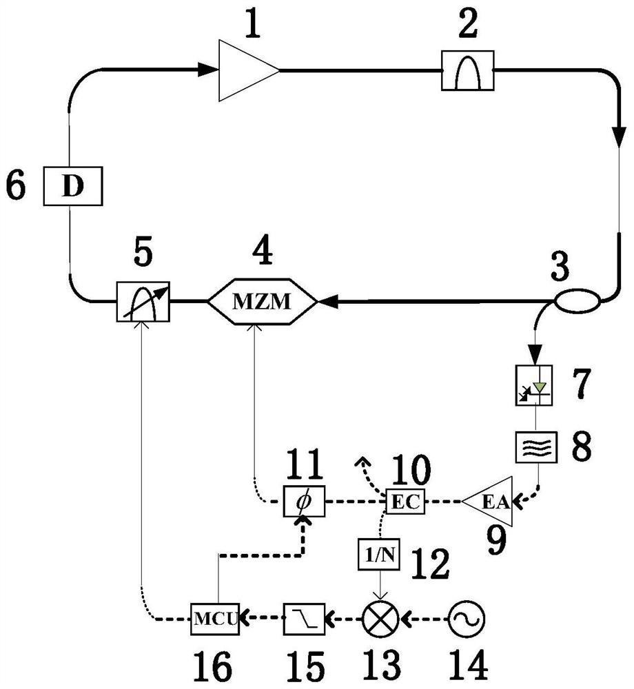
Figure 1 from A frequency tunable super Circuit Diagram
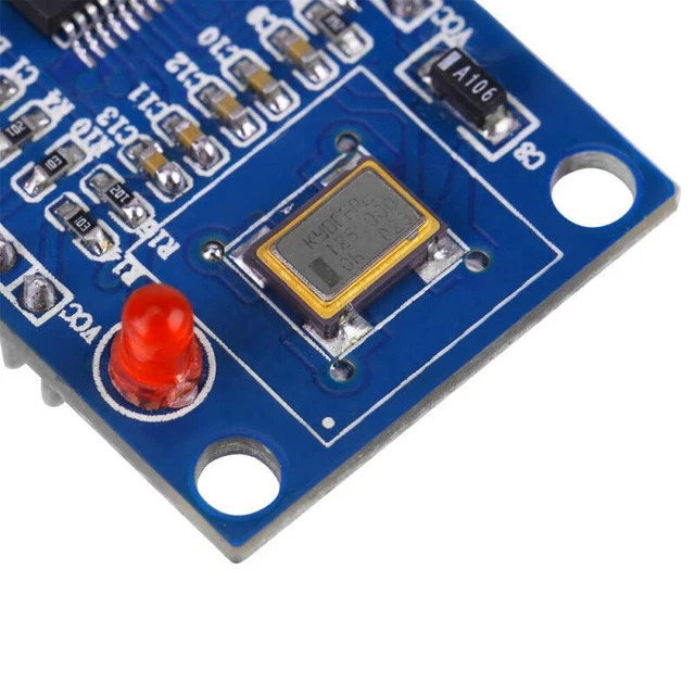
Figure 1 from A frequency tunable super Circuit Diagram You typically use one of the many cheap RF synthesizers which include an oscillator, a (very advanced) PLL and an interface to receive a lower-frequency reference from e.g. an external quartz oscillator, or to drive a quartz itself to generate a low-frequency reference. The output signal of the RF generator is an analog sine (AM modulated or not modulated ) signal. At high frequencies its amplitude decreases a lot. To be able to measure the frequency of the signal with the frequency counter a pre-amplifier / signal form shaper is needed. I took the circuit presented here and soldered it on small perfoboard.

First, start with a high-frequency oscillator circuit that generates a square wave or DC pulse. We chose TTL digital IC because it works flawlessly at a high frequency of up to 20MHz. The circuit below is a simple crystal oscillator circuit using 74LS04 as a main component coupled with a crystal and two resistors instead of an RC network circuit. The signal generation process starts with the oscillator, whichgenerates a stable and repetitive waveform, A radio frequency (RF) generator generates high-frequency signals in the radio frequency spectrum, typically ranging from a few kilohertz to several gigahertz. These generators are crucial for various applications in wireless
How to create high frequency signal? Circuit Diagram
\$\begingroup\$ @Parisa if you need better performance (performance not stated in question) then choose a better VCO. The point of this answer was to show what is possible. This topology (i.e. using a PLL) is probably going to give the best results for most applications but, if you are not too bothered about centre-frequency drift, look for a VCO that has much finer tuning and run it open loop

If the frequency is too low, you will get visible flickering on the LED, and if too high, the control device or the load will not be able to turn on and off fast enough. We have seen how to build a simple astable oscillator with the 555 timer that generates a pulse width modulation signal to control any any analog device.
Generating high frequency sine wave (up to 100MHz ... Circuit Diagram
1. Sinusoidal Oscillators - these are known as Harmonic Oscillators and are generally a "LC Tuned-feedback" or "RC tuned-feedback" type Oscillator that generates a purely sinusoidal waveform which is of constant amplitude and frequency.; 2. Non-Sinusoidal Oscillators - these are known as Relaxation Oscillators and generate complex non-sinusoidal waveforms that changes very quickly
The oscillator circuit we will build with a 7414 schmitt trigger inverter chip to produce a 1Hz signal is shown below. on the other hand, if you want a very high-frequency signal, you would use a small resistor and a small capacitor, such as a capacitor in the picofarads. When you have a capacitor in the picofarads, it can only hold a small
