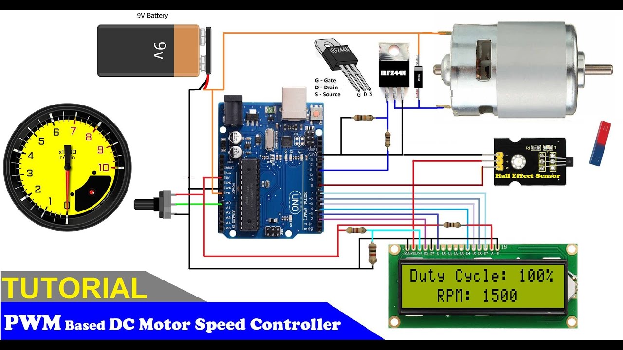
PWM Based DC Motor Speed Control using ARDUINO Microcontroller 2019 Circuit Diagram
PWM Based DC Motor Speed Control using ARDUINO Microcontroller 2019 Circuit Diagram In this tutorial, we'll guide you through an innovative engineering project to control the speed of a high RPM DC motor using PWM (Pulse Width Modulation) with an Arduino Uno, a TIP122 transistor, and a 16×2 LCD display. This project is designed for engineering students and hobbyists seeking hands-on experience with Arduino and electronics.
Arduino PWM Motor Control DC Motor Speed Control - Download Program. Download Program/Code. In the beginning of the code two integers are declared by name "out1" and "val", where out1 is equal to 9 which shown that pin D9 of Arduino is used as output pin (or PWM pin). Moreover, data coming from the serial monitor saved in the second

ACS712 Current Sensor with Arduino Circuit Diagram
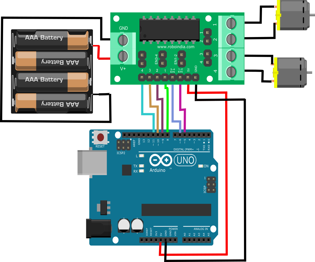
For higher rated voltage/current you need to use motor driver IC like L293D. See DC Motor Control using ATmega32 and L293D for example. Video demonstration of Potentiometer controlled PWM signal generation using Arduino to control the Speed of a DC motor. The video below demonstrates how we can use a potentiometer to control speed of DC motor In this tutorial i'm going to show you how to control the speed and direction of two DC motors by the most common method PWM signals. DC Motors Control Using Arduino PWM with L298N H-Bridge Components and supplies. 1. Arduino UNO. 1. Dual H-Bridge motor drivers L298. 1. DC Motor, Miniature. Tools and machines. 1. Servo Motor, Premium Male
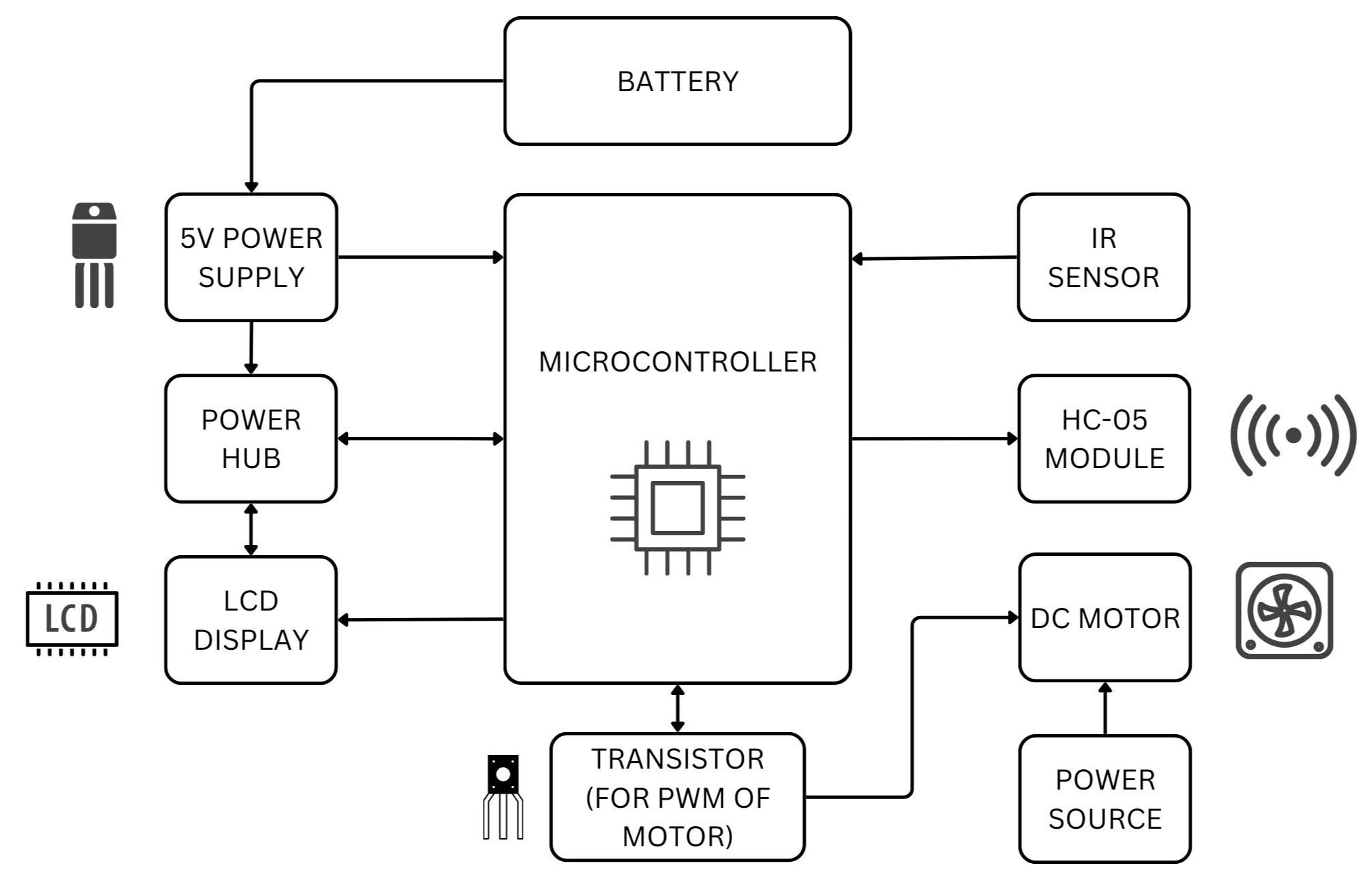
In this guide, you'll learn how to control the speed of a DC motor with Arduino using the powerful PWM (Pulse Width Modulation) technique. PWM is a highly efficient method for adjusting motor speed, allowing you to precisely control the rotation speed of your DC motor, from a complete stop to full speed.
DC Motor speed control and measurement Circuit Diagram
Setting Up the Basic DC Motor Control Step 1: Connect the Components. Hook up your Arduino Uno to the breadboard. Connect the DC motor to a PWM-capable pin (e.g., pin 9 or 10). Add a flyback diode across the motor terminals for safety. Step 2: Arduino Code for the PWM Signal. Here's the Arduino code snippet to control motor speed: Learn how to control DC motor speed and LED brightness using PWM (Pulse Width Modulation) with Arduino. See circuit diagrams, programs and examples of PWM control using arduino.